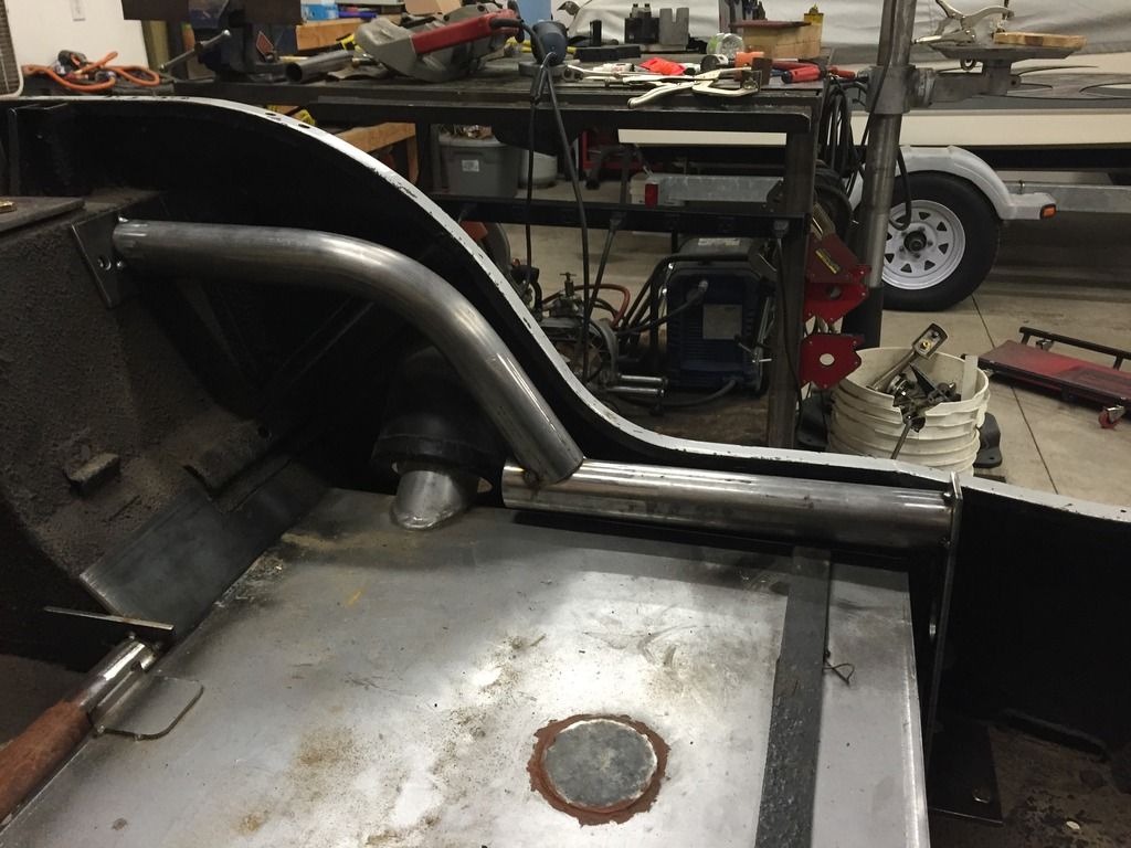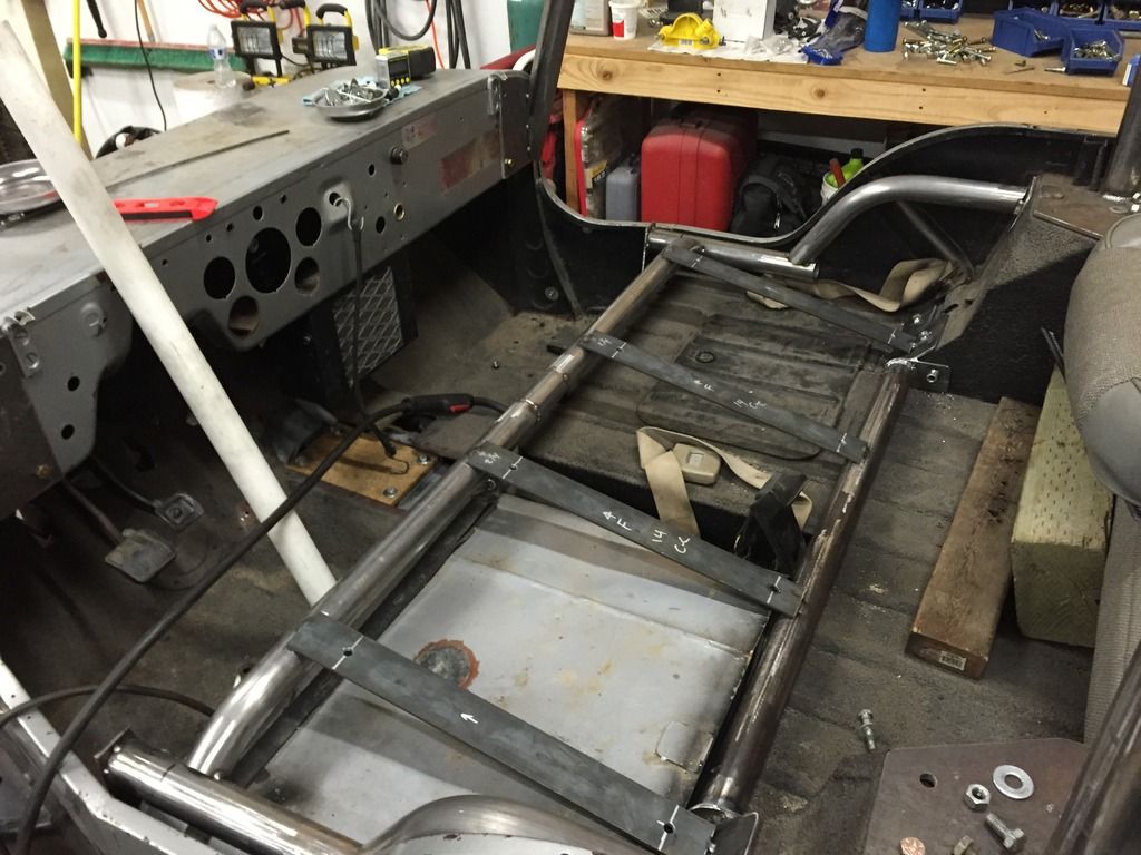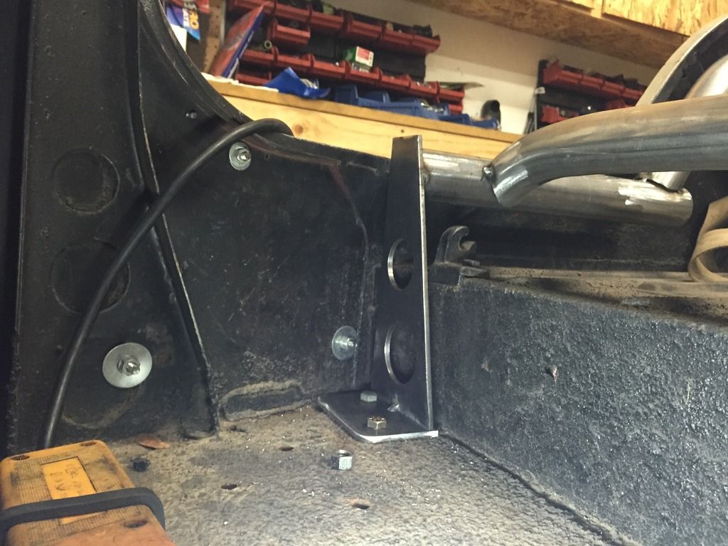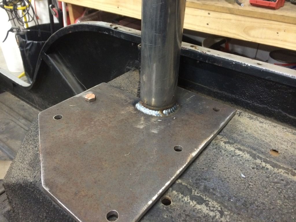
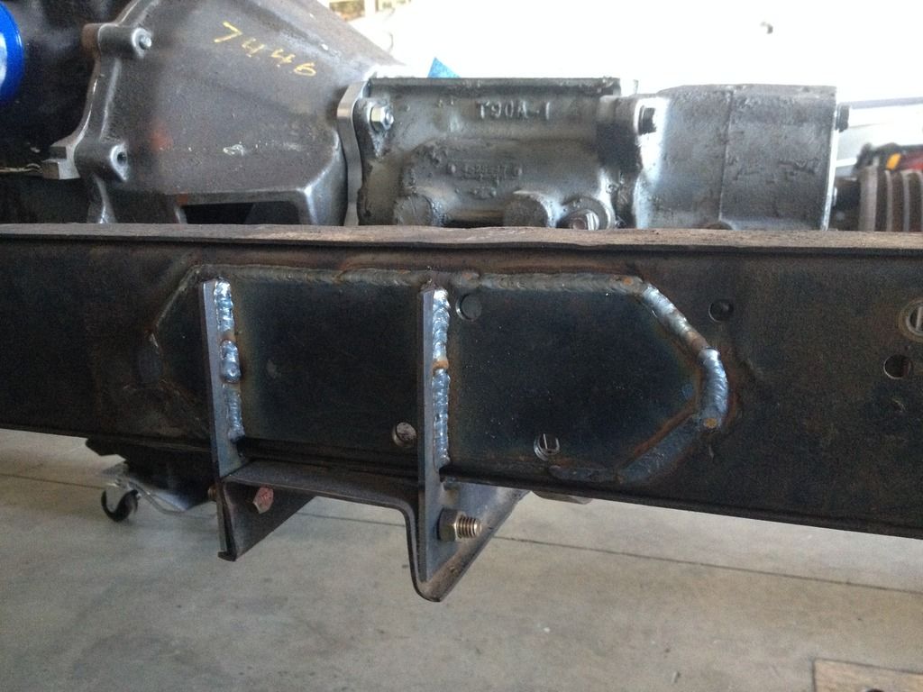
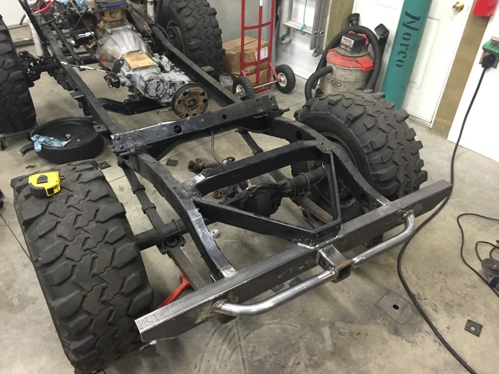
Once I had the motor firmly located, I turnt my attention to the transmission crossmember. The final location of the engine was about 2” forward and 1-1/2” toward the passenger side of the original, so the crossmember had to go along with it. The biggest problem with that was the mid-ship body mount was directly between the vertical ears of the original crossmember mounting tabs, so I had to get creative when fabricating the new crossmember mount tabs and body mount relationship:
Once the welds cooled, I pulled it outside and gave the chassis a good bath with some purple cleaner and a scrub brush:
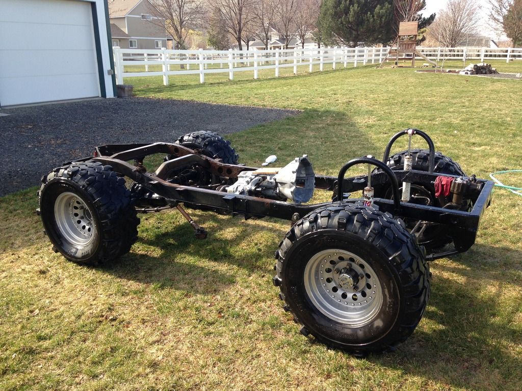
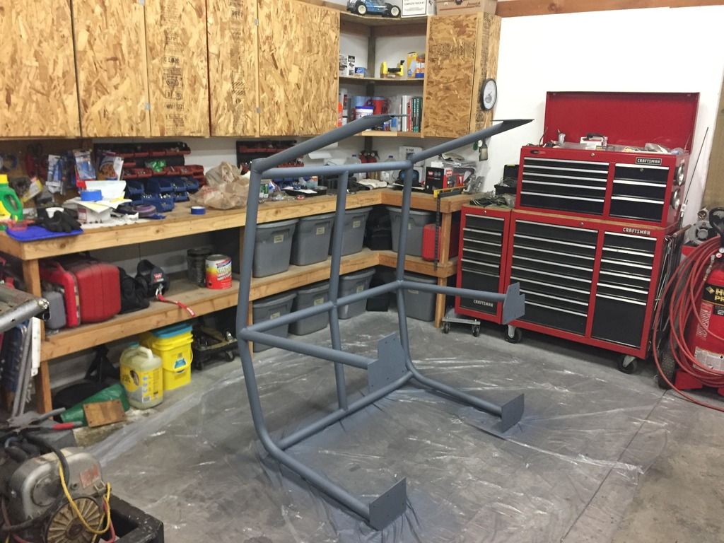
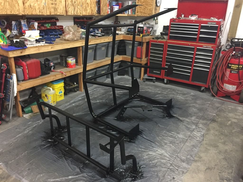
I then shot the chassis with a quick coat of Rustoleum’s finest satin black:
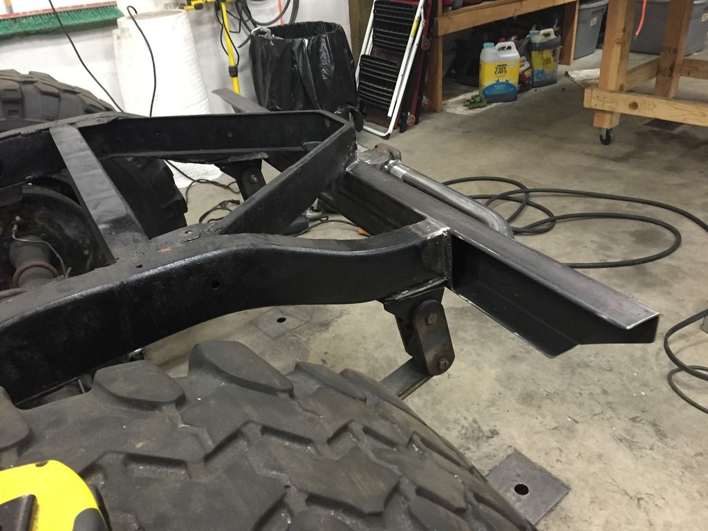
At that point I stood back to look at the mess I had created, and realized that I had ruint just about every aspect of the original chassis, with the exception of the rear crossmember/bumper. Why leave it out of the fun? So out came the plasma cutter, tube bender, and hot glue gun. I removed what was left of the original rear crossmember/bumper, and took a section of 2”x4” box tubing and opened up the ends to mimic the original. To that I added my now patented rear receiver/tube step combo, and voila:
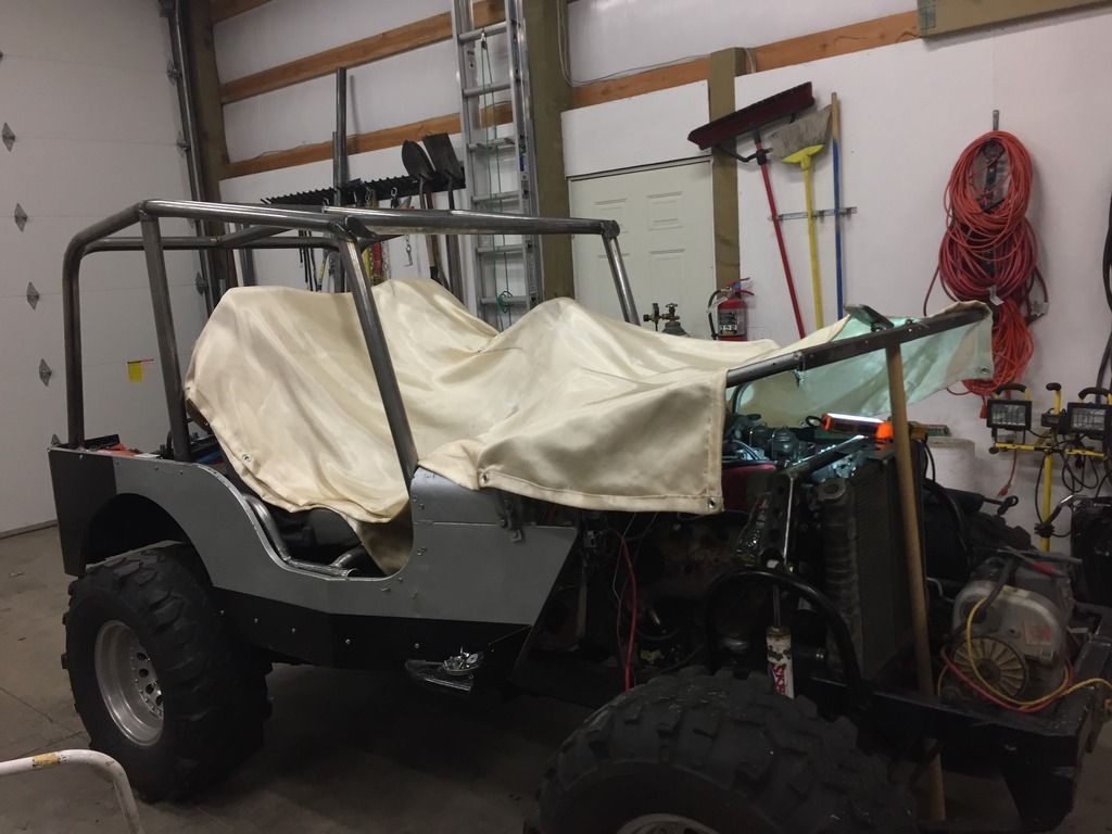
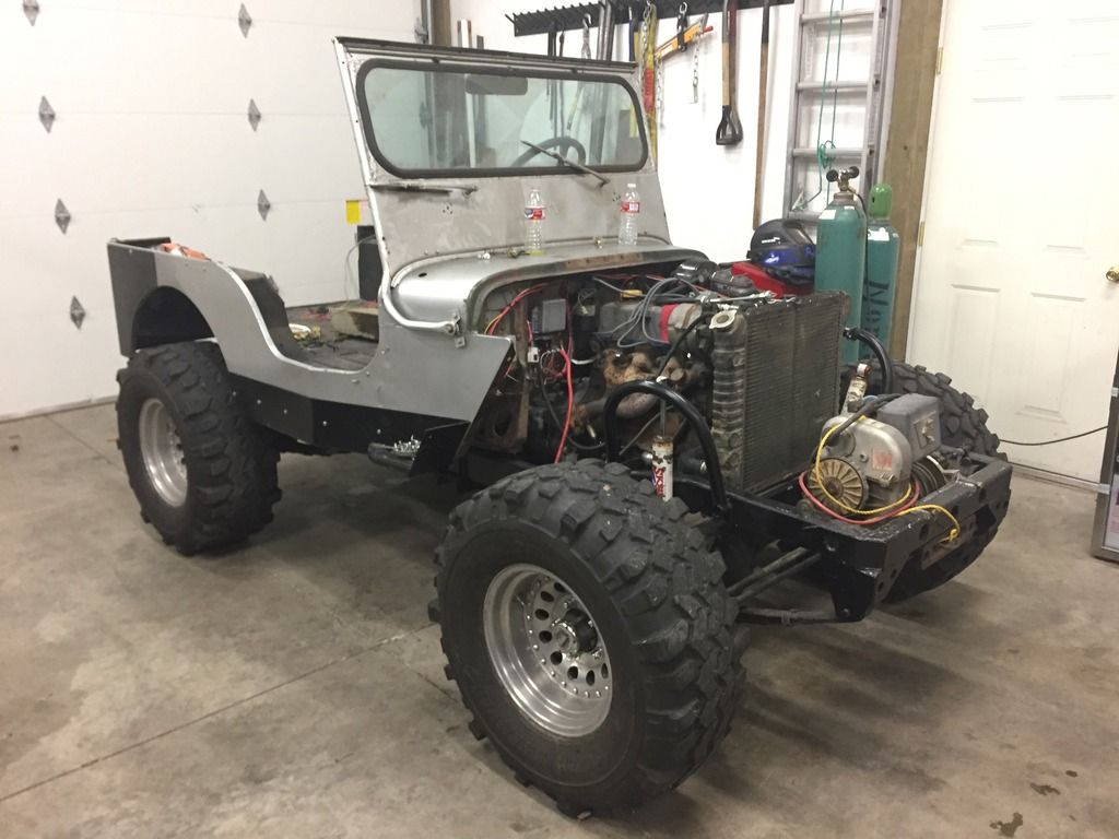
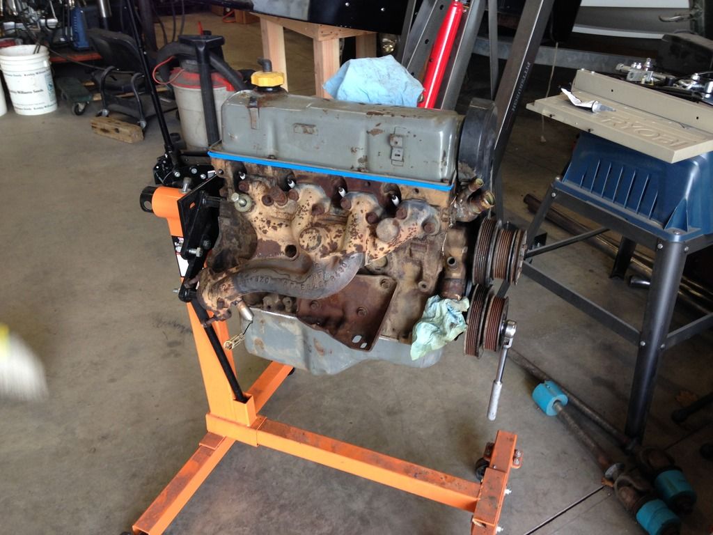
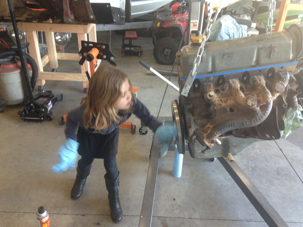
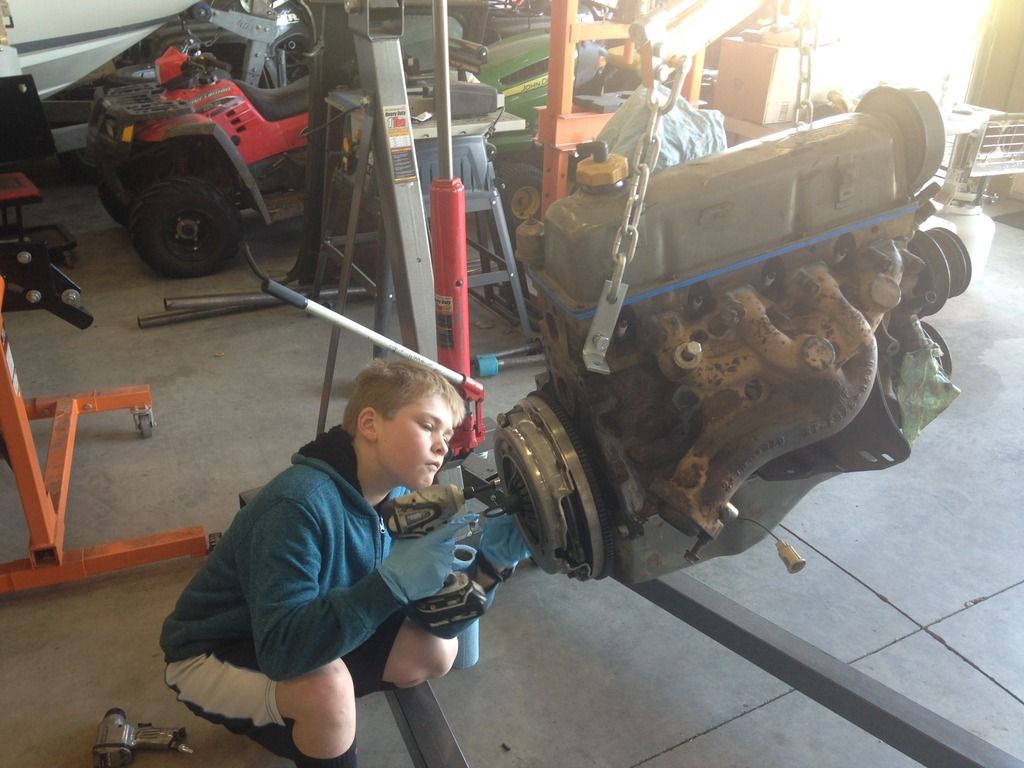
While I performed some admittedly scary rigging and got the body mounted back on the chassis, I put the minions to work cleaning up and resealing the Ford 2.3L powerhouse, and mounting up the new flywheel/clutch/pressure plate combo:
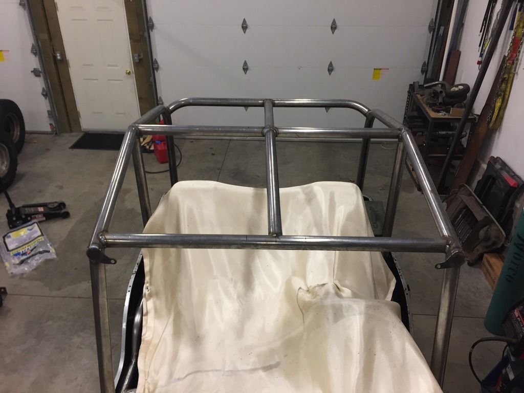
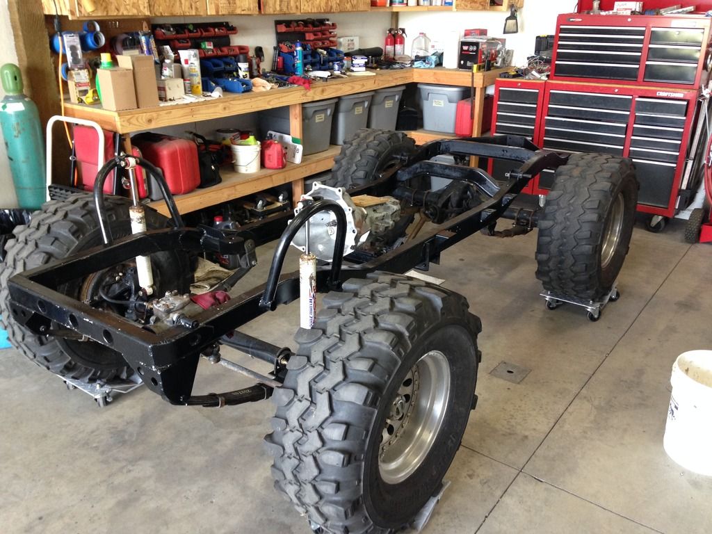
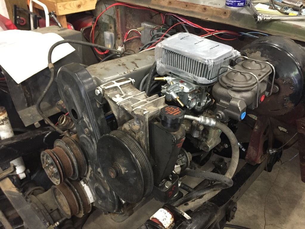
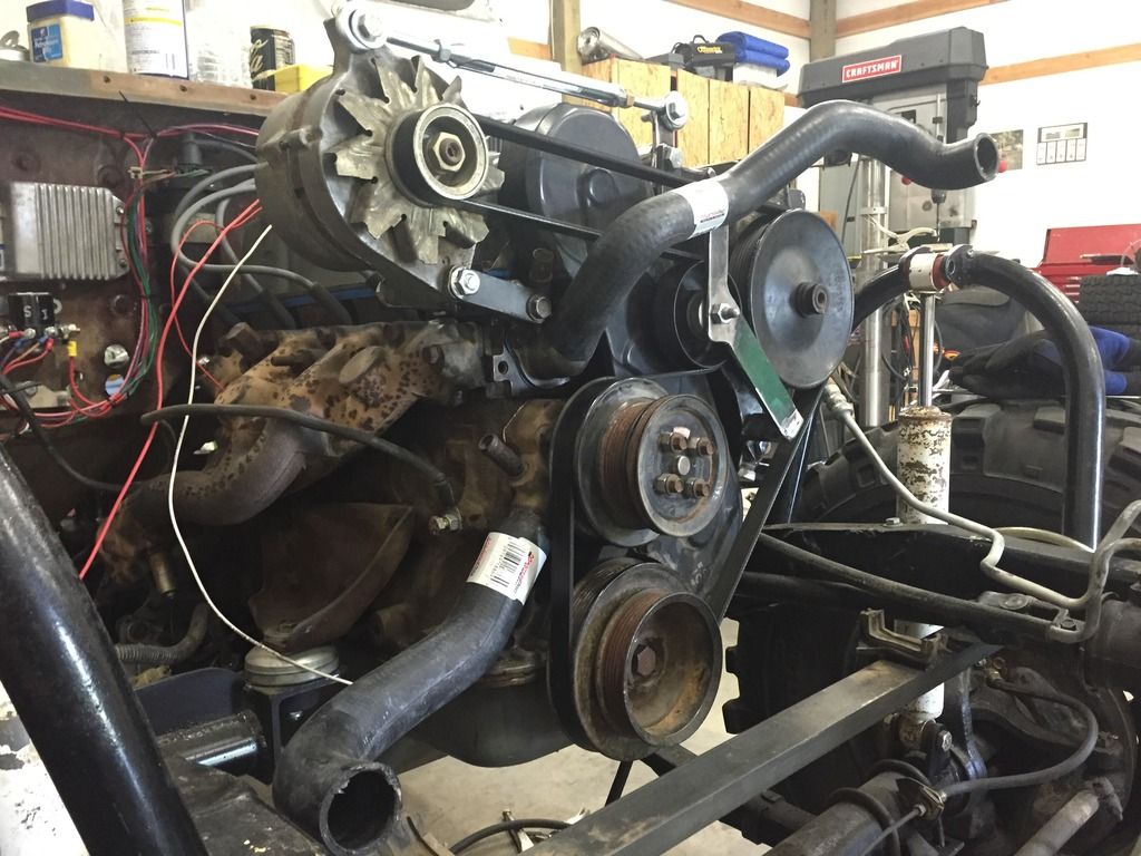
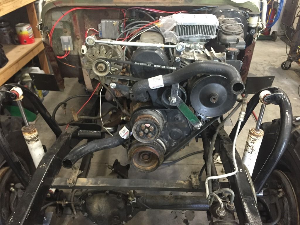
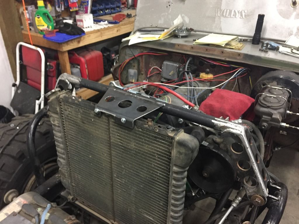
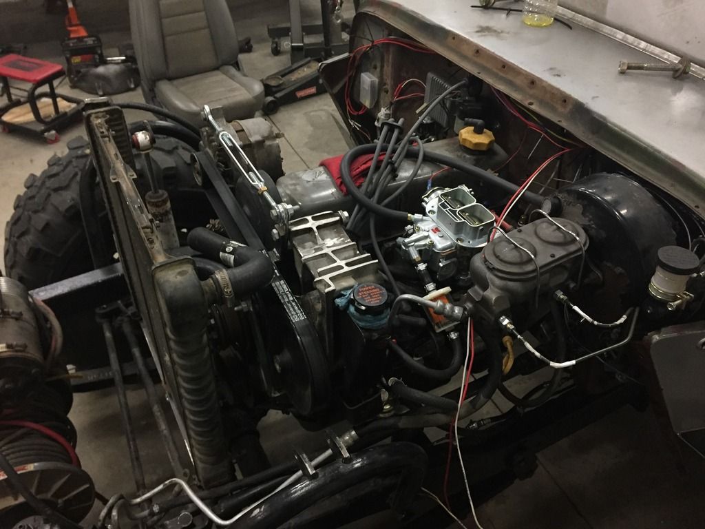
So now the drivetrain was sitting in the chassis and the body was, again, temporarily on location. This allowed me to verify firewall and transmission tunnel clearances and make some minor adjustments. It also allowed me to visualize radiator location and get a handle on how that was going to be mounted, and get a start on power steering pump mounting, alternator mounting, and belt routing. A few frosty beverages and grinding buggers later, we have bonefied mounts for the radiator and all engine driven accessories:
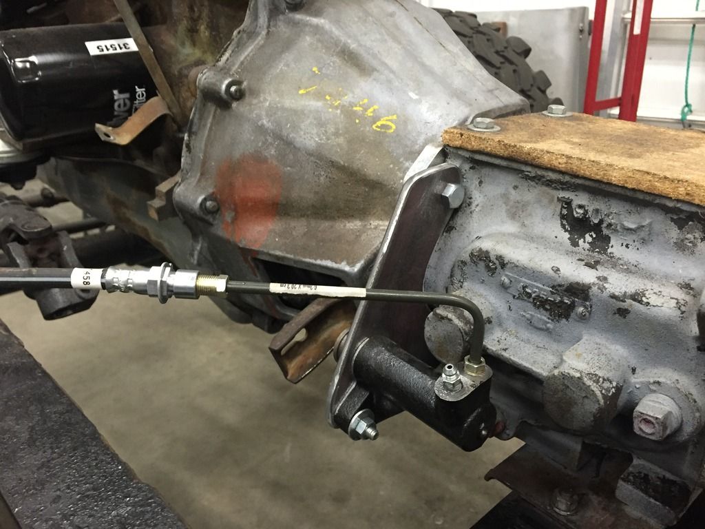
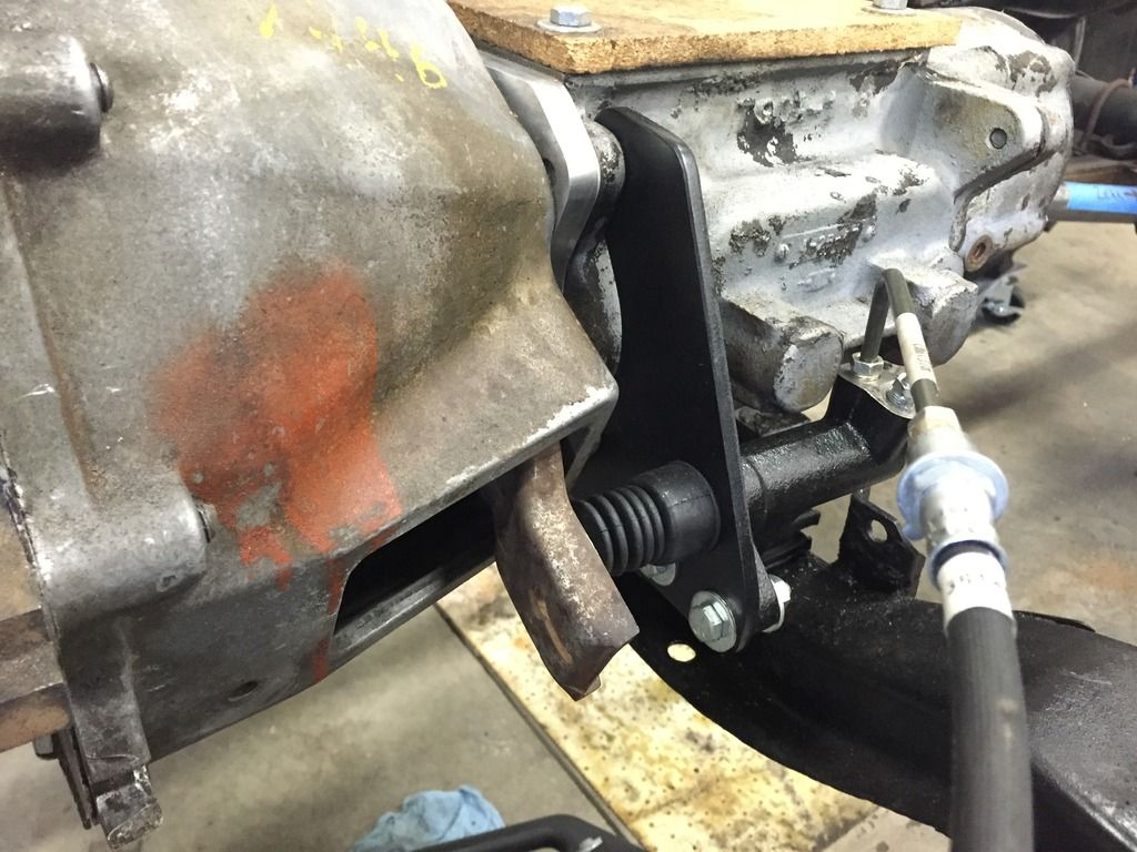
With that handled, I turnt my attention to hydraulics. Converting to hanging pedals and a hydraulic clutch was something I had dreamt about for years, and at this point I could visualize the concept. Some CAD (cardboard aided design) allowed me to fabricate a mount for the clutch slave cylinder, and with the body still temporarily on location I could conceptualize hose routing and make a parts list:
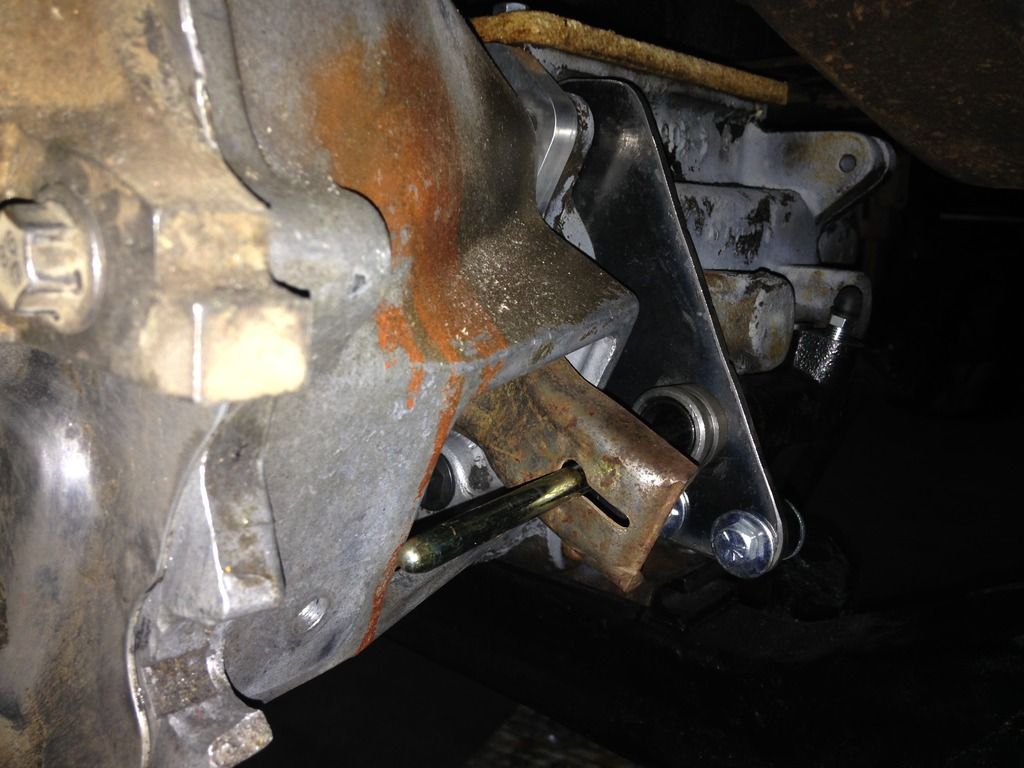
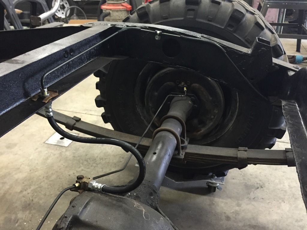
I pulled the body back off, and went to work finalizing he clutch slave cylinder mount and running rear brake lines:
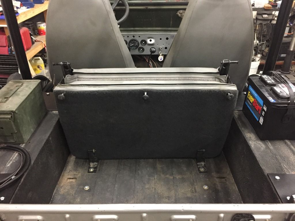
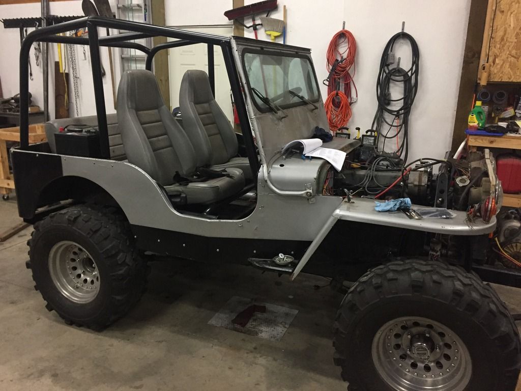
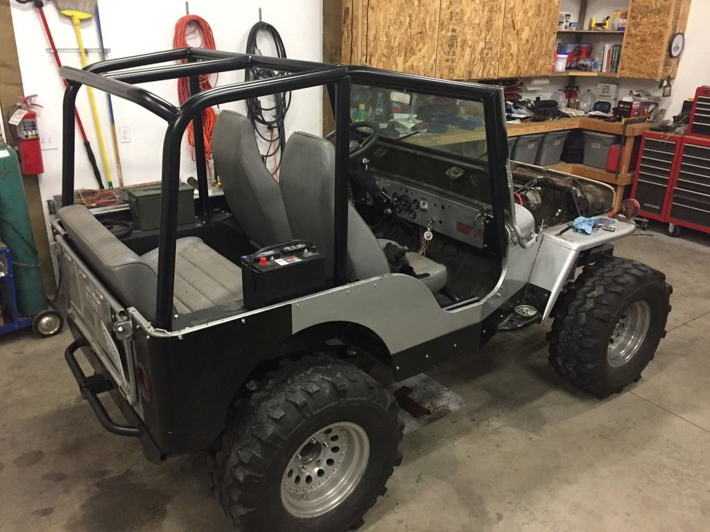
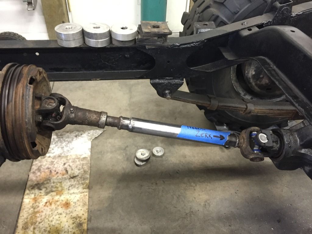
One more time dropping the body onto location, this time for reals. However, before lowering it into position I took the time to modify the rear driveshaft while access was the easiest, and you can also see the 1” aluminum pucks for a minor body lift to help accommodate transmission clearance in its new home:
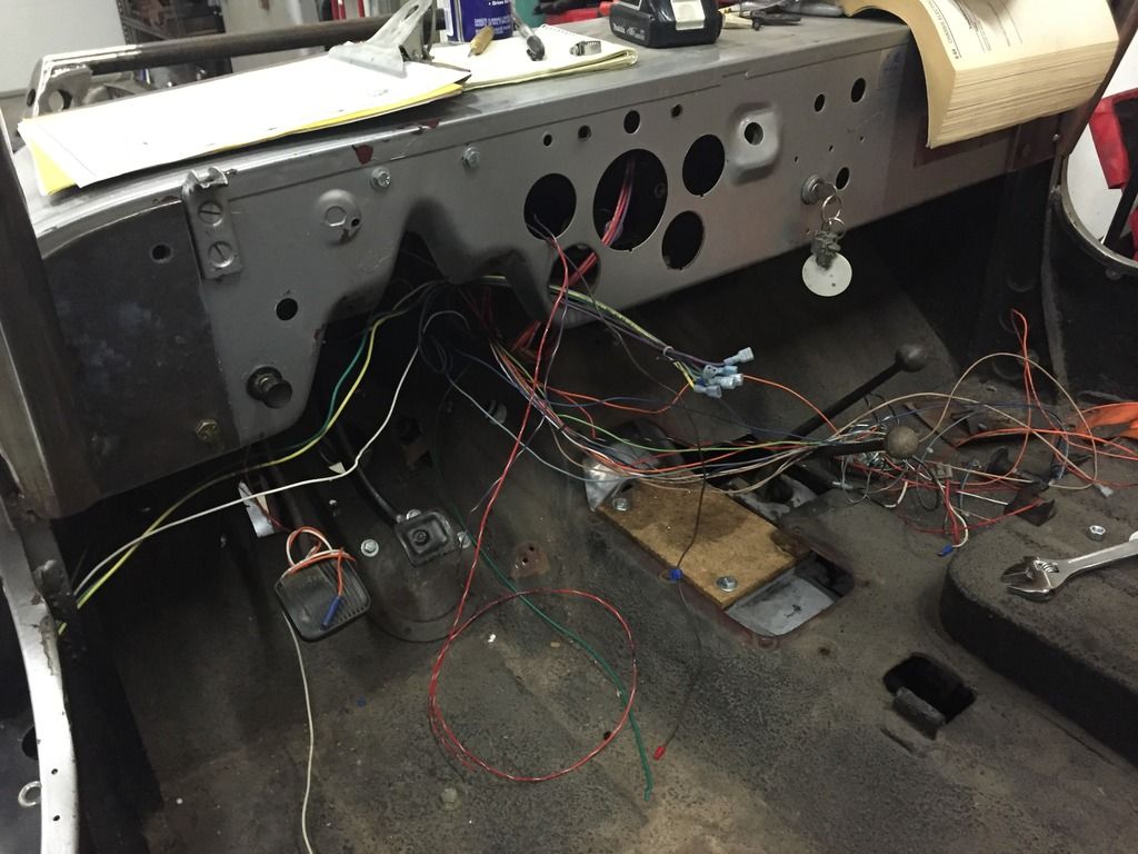
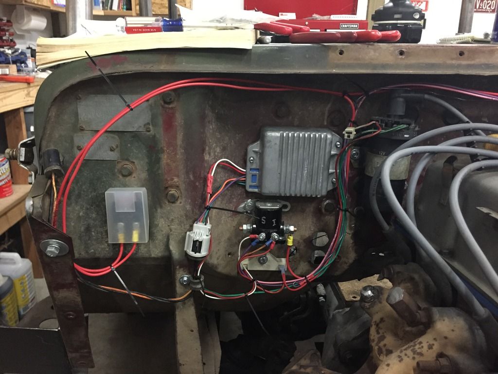
So now the body was on the for the final time, it was time to finish all of the plumbing and start the wiring. Yuk…
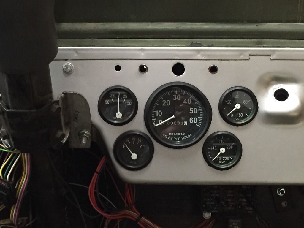
I found a good looking set of gauges from a vendor on eBay and decided to give them shot:
After trying to clean up the Motorcraft carb several times, I just couldn’t get it to a point where fuel would flow properly, so to the trash can it went. I ordered up a brand new Weber 32/36 and could not be happier with the decision:
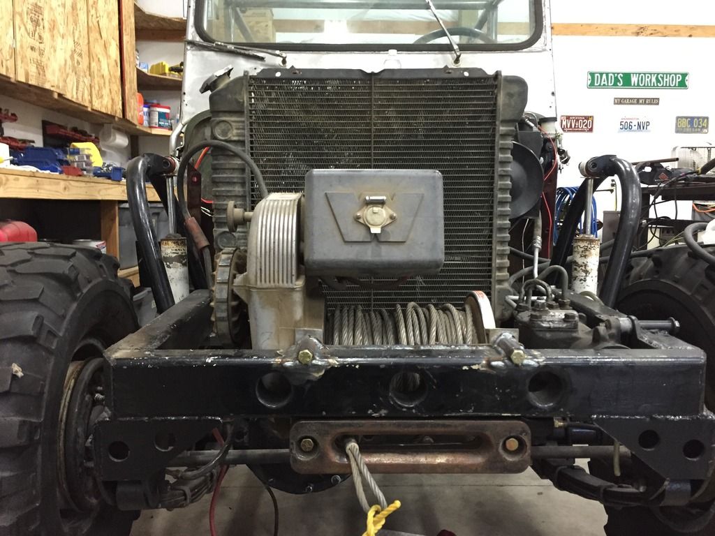
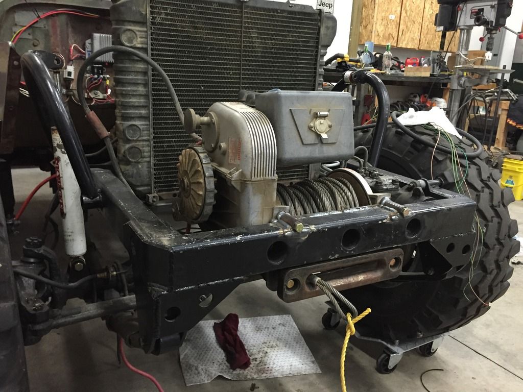
During one evening of long-overdue shop cleaning, I stumbled upon a large object that had been hidden by other rubbish for quite some time. After dusting the aforementioned object off, I realized it needed a new home, and it just so happened that my beloved flatty could provide that home. So, again with the plasma and hot glue gun, and a new home was made for it. Yep, “it” was a Warn 8274: