I am running a Hobart Handler 135, .023 wire, Stargon. I love the way it welds. If going real thin, you can just pulse the trigger and it can come out clean enough to almost look like a continuous weld.
A&L are real good people for supplies. Cheapest for bottle refills that I have found, quite considerably.
Yet another slow build thread. . .
-
White trash

- Posts: 1763
- Joined: Tue Jan 22, 2008 9:38 pm
- Location: El Pasco
OldGreen wrote:
I'm also using .023 wire. At least on the side of the machine, it maxes out at 3/16 regardless of what wire you use and the .023 is easier for me to control. . .ie, go SLOW. . .
Either way, it is almost time for a refill.
.023 can't carry the amperage that .030 or .035 can. It's a great thin metal wire though. I use .030 on chassis type welds.
Roman wrote:weldingweb.com/ wrote:100% CO2 is going to provide a more violent and hotter arc which would pose problems on thin material
The penetration difference is minimal and the arc instability of C02 makes a big difference whether an amateur or a seasoned welder... I think "violent" was the proper term!
The penetration difference is important when using a lower amperage machine. You need all the help you can get with a 110 unit.
Flux core has better penetration yet but flux core SUCKS to deal with. I have a good friend that is a welding inspector for a large structural welding shop in Portland. He refuses to use anything but flux core since he runs a 110 machine. He throws down some nice looking welds with it but he spends just as much time cleaning the welds as he does preparing to do them in the first place.
Now back to the program. . .
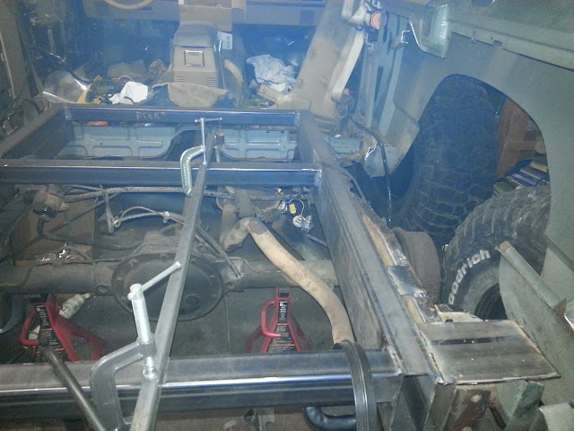
Tonight might not LOOK like much.. .but it was actually a really big deal. I only had about an hour or so in the garage so I didn't get to really get finished, but I was able to tack the new section of frame in to place and get rid of my ratchet strap crossmember. . .for now. The theory is, that if I decide to cut the tacks and remove the frame to do something. . .that I just have to line the pieces back up and burn it it. Anywho. . . the few lessthanexciting pics:
Tacked this little chunk of flatbar on to hold stuff together. It had to be far enough forward on the chassis not to interfere with plating the shackle hanger but far enough back to hold everything together. I also tacked the bottom of the old frame rail to the bottom of the new one.

Other side. . .same story.

Now the "kinda" interesting part. I am going to run the factory rear swaybar for now but all of its structure is gone. As it turns out, it shares structure with the rear shoulder belt anchor. The bad news is that I have to cut the "nose" off of my little brace. There will be molten metal bondo to make it prettier. . .but you guys are friends. . .you understand. Again, the old frame is only tacked, but I went ahead and burned this one into the new frame. Only had time to make one before I came inside.

One more pic so you can see what's going on inside the cab.

Tonight might not LOOK like much.. .but it was actually a really big deal. I only had about an hour or so in the garage so I didn't get to really get finished, but I was able to tack the new section of frame in to place and get rid of my ratchet strap crossmember. . .for now. The theory is, that if I decide to cut the tacks and remove the frame to do something. . .that I just have to line the pieces back up and burn it it. Anywho. . . the few lessthanexciting pics:
Tacked this little chunk of flatbar on to hold stuff together. It had to be far enough forward on the chassis not to interfere with plating the shackle hanger but far enough back to hold everything together. I also tacked the bottom of the old frame rail to the bottom of the new one.
Other side. . .same story.
Now the "kinda" interesting part. I am going to run the factory rear swaybar for now but all of its structure is gone. As it turns out, it shares structure with the rear shoulder belt anchor. The bad news is that I have to cut the "nose" off of my little brace. There will be molten metal bondo to make it prettier. . .but you guys are friends. . .you understand. Again, the old frame is only tacked, but I went ahead and burned this one into the new frame. Only had time to make one before I came inside.
One more pic so you can see what's going on inside the cab.
Some kinda random stuff from the last few days. . .
Got the mounts to the old seatbelt standoffs done (and, therefore, the rear frame is in forever)

So I moved on to boxing the shackle hangers:

One interesting thing to note is that the two sides of an XJ's shackle mount aren't level.. .doubled up sheetmetal and bends in the floor are the cause:

What yo also see on the right side of that pic is all that is left of the rear "structure". That little piece of the rear crossmember is all that is locating the bedsides right now.
The next step is to build the bumper/outer rear crossmember, then the rear shock mounts, then on to the cab area frame rails and rockers.
Time is SHORT for Camp Schamp. . .but I'm determined!!!
Got the mounts to the old seatbelt standoffs done (and, therefore, the rear frame is in forever)
So I moved on to boxing the shackle hangers:
One interesting thing to note is that the two sides of an XJ's shackle mount aren't level.. .doubled up sheetmetal and bends in the floor are the cause:
What yo also see on the right side of that pic is all that is left of the rear "structure". That little piece of the rear crossmember is all that is locating the bedsides right now.
The next step is to build the bumper/outer rear crossmember, then the rear shock mounts, then on to the cab area frame rails and rockers.
Time is SHORT for Camp Schamp. . .but I'm determined!!!
-
79chevy39.5's
- Posts: 1204
- Joined: Wed Apr 11, 2007 7:48 pm
and moving on to the rear bumper. . .
Marking it up. The idea was to cut a pie shape out of it so that I could bend the lower rail back up and keep the radius.

and the first cuts. . .looks like a whales mouth more than a pie piece.

From experience and, well, math, I knew that the flat piece needed to be left longer. I didn't bother figuring out how much. As it turn out it was long enough to ALMOST cap off the end as well. that wasn't part of the plan but. . .what the heck!! I still have about 3/4" of an inch to close out.

So, that is how far I got in 2 hours. I marked the other side for the cuts as well and marked off the spot for the receiver. I'm still not convinced of my final recovery point set up for the rear so I may delay making that cut until the bumper is mounted. I'm going to finish up the bumper tonight and maybe even get the tube for under the rear quarters done up. Then I have to mount it. . .
After that, I am going to figure the rear shock mounts and move on to the front frame. Hopefully I'll have the main rails at least mocked up by Sunday evening if not further than that.
The goal is to have all of the tube steel minus the cage and sheet metal done by Feb. 1 in order to meet the deadline.
Marking it up. The idea was to cut a pie shape out of it so that I could bend the lower rail back up and keep the radius.
and the first cuts. . .looks like a whales mouth more than a pie piece.
From experience and, well, math, I knew that the flat piece needed to be left longer. I didn't bother figuring out how much. As it turn out it was long enough to ALMOST cap off the end as well. that wasn't part of the plan but. . .what the heck!! I still have about 3/4" of an inch to close out.
So, that is how far I got in 2 hours. I marked the other side for the cuts as well and marked off the spot for the receiver. I'm still not convinced of my final recovery point set up for the rear so I may delay making that cut until the bumper is mounted. I'm going to finish up the bumper tonight and maybe even get the tube for under the rear quarters done up. Then I have to mount it. . .
After that, I am going to figure the rear shock mounts and move on to the front frame. Hopefully I'll have the main rails at least mocked up by Sunday evening if not further than that.
The goal is to have all of the tube steel minus the cage and sheet metal done by Feb. 1 in order to meet the deadline.

Oh no... Jim, you didn't!
You were even my test dummy
1/8" is fine for frame rails, but bumpers need to be 3/16", you already dented one.
But other than that, looks good. Cut out the receiver tube. I would add "main" recovery points inline with the frame rails (for hard pulls) but the receiver will probably get the most use!
Roman wrote:Oh no... Jim, you didn't!
You were even my test dummy
1/8" is fine for frame rails, but bumpers need to be 3/16", you already dented one.
But other than that, looks good. Cut out the receiver tube. I would add "main" recovery points inline with the frame rails (for hard pulls) but the receiver will probably get the most use!
I figured I'd get that from you.
That bumper DESERVED to get dented. Actually, not true. . .it was too pretty to get dented. It was abused. . .
I'm still not completely convinced of the right rear recovery point strategy. . .I may just wait and see how it comes out.
-
79chevy39.5's
- Posts: 1204
- Joined: Wed Apr 11, 2007 7:48 pm
ive started to cut the mounting points through the bumper and make the ends one side of a shackle mount and then weld another plate along that on the outside (similar to what you did to make a thicker piece of steel for a dring shackle mount) that way its not trying to pull the tube apart and gives it another anticrush support much like the reciever tube will be aswell (also not making thicker tube manditory)
the next bumper i make will also have cutout for highlift (similar to nicko's bumpers on his Scout)
the next bumper i make will also have cutout for highlift (similar to nicko's bumpers on his Scout)
If you look at mine, I only have the center receiver (right now) but mine is 1/4". Not worried about taco'ing this one.
But one GREAT thing about the receiver is you can plug a d-ring stinger in there...
While that doesn't sound all that great, when you stretch your winch line UNDER your jeep and run it through the d-ring, you can winch yo a$$ sideways outta the two trees you (I) got myself wedged between!
But one GREAT thing about the receiver is you can plug a d-ring stinger in there...
While that doesn't sound all that great, when you stretch your winch line UNDER your jeep and run it through the d-ring, you can winch yo a$$ sideways outta the two trees you (I) got myself wedged between!
Roman wrote:If it's not welded on yet, go get a 60" piece of 3/16...
It is 64" and no.
Here's it hanging on by one C-Clamp. The fender skins are bowed out because they are only held on by the B pillars at this point. The bumper actually stick outside the body by just a smidge over an inch just like the front bumper. The rockers, on the other hand, will be at almost 2". . . Yes, it needs a little more clean up and isn't done, but I wanted to hang it up there and take a pic before I went in the house last night.

I think that a solution for the recovery points has been engineered. It also takes care of a few other things and is different than anything I've seen before. Of course. . .most of this is slightly different or at least an amalgamation of things I've seen.

Here is an idea of what the rear shock mounts will look like. Once I decide on the actual shocks I want to use, I'll put them on the frame side. I will probably use the ones that are on there for now but I will be limited in down travel. I'm planning on using 10" shocks in the rear and those ones are 8.5". Now that I type this, I remembered that I think I have a 10" shock in the garage. . .


And. . .just like that I changed my mind. There is a 4" difference in the shocks I want versus the ones I have. So.. .I'm leaving the shock mounts off until I get the rear subframe tied solidly into the main frame rails. Then I'll take it out in the driveway and lift a tire on the air jack to measure for shocks and bumps. . .I am pretty sure that the mounts will end up at least 3 or 4" taller than they are in the mockup above.
-
Wrench
- Peak Putters Member

- Posts: 1237
- Joined: Sat May 30, 2009 7:23 am
- Location: in a van down by the river
Not sure what rear shocks you are using but...
The ones I used were Rough Country, valved for a stock Cherokee. The stock Cherokee setup has the shocks angled over, which lessens the damping effect of the shocks, and they worked well in the stock location. When I mounted mine straight up and down, they were quite harsh on both compression and rebound, unless the Cherokee was loaded heavy for a trip. I had very noticeable "packing" of the rear and loss of traction when running whoop sections. Running a light setup and having the shocks straight up and down, you will either need to find shocks you can tune the valving in, or find some valved for a lighter vehicle.
Also, at that location, your tire will most likely hit the shock or mount at full flex (axle completely crossed up). Not sure how to easily test that with leaf springs, though.
Paul
'84 XJ, '19JL
'84 XJ, '19JL
Wrench wrote:Also, at that location, your tire will most likely hit the shock or mount at full flex (axle completely crossed up). Not sure how to easily test that with leaf springs, though.
Easiest way I have found is to disassemble the spring pack and just mock it back up with only the main leaf... Then you can stack up blocks, lift one side with a jack/cherry picker, whatever. Helps set bumps, measure shock lengths, and czek for clearance, Clarence.
Yep, I've wheeled one of those, too...

tobyw wrote:Wrench wrote:Also, at that location, your tire will most likely hit the shock or mount at full flex (axle completely crossed up). Not sure how to easily test that with leaf springs, though.
Easiest way I have found is to disassemble the spring pack and just mock it back up with only the main leaf... Then you can stack up blocks, lift one side with a jack/cherry picker, whatever. Helps set bumps, measure shock lengths, and czek for clearance, Clarence.
Yep. . .for the record, there is no way in heck that it would clear right where it is sitting. This is the exact reason vice grips were invented.
At some point last week I got the shackle hangers nearly done. . .well. . .done for now. There is still one more "area" to tie in that I can't do until I get to the sheetmetal portion of our program. You can see that the forward mating surface is still unplated. I won't apologize for the welds. . .on a few that I screwed up and had to grind out, they were certainly good enough for the girls I date. Again, this will see some flap disc love but you guys won't judge me:

And now for the "if I screw this up I have to buy another two door xj and start over or take the one I bought for Will and try not to screw that one up" Moment. . .
After some CAREFUL measuring, it was time to build the first "main" frame rail. I can't lie. I spend more than half of the day staring at it. I'd make a measurement, make it again, stare, stare, make it one more time, make a cut, stare some more. . .
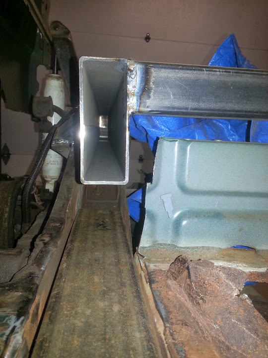
Then I broke out the chop saw, put on a new wheel, cut the 3x3x.120 and then marked up cut, bent and tacked the angles. One side is in the footwell and the other side goes quite a ways into the bed area because of the angles. The forward side goes from 3" to 1/8" in 9" and the back side takes 7. . .but both had to have the noses trimmed and a nip/tuck because of the curves and brackets on the original uniframe.

The factory uniframe rail has a tiny "dip" in it under the seats. The original plan was to cut/bend/weld the 3x3 to fit. However, when I did the test fit, the rail was so close to perfect that I decided to forgo the extra work and extra cuts/welds.

I'm pretty happy with that part so far. There are a couple of things to note:
1. The factory rail has a "hat" on the bottom that prevents the 3x3 from seating all the way to the bottom. It is less than a 1/4" deep at the rear and then around 1/2" in front of the "dip". . .Today, I don't care, but it would be pretty easy to cut the factory rails out completely at some point. They do, however, provide stiffness and very handy captured nuts for the skidplate.
2. There is a 1/4" gap on the outside of the box tube. There are a couple of thoughts about how to fill it. One thought would be to not fill it at all and just sheetmetal over the top. That would likely be fine, but I want to drill holes in the outside of the factory rails and weld them to the new rail. So, I could make some 1/4" shims out of 1 or 1.5" flat bar and weld them to the 3x3 at the right locations. Last option would be to weld a 5' long chunk of 2.5" x 1/4" flat bar along the length of the rail. That way I could make it flush with the top and not need any sheetmetal at all in that area after grinding and seam sealing. . .but it would be kind of heavy. . .but EASY. I like easy and functional so I "think" I have decided to go that way.
Before I yank it out to prep it, I have to mark the spots for clearance holes for the crossmember bolts and the main spring bolts. I am also putting together a strategy to tie the main rails into the rear subframe and the spring hangers. I think I have that figured out but you'll have to wait and see.


I keep forgetting to put the seam on the inside. . . That corner IS square though. . .just the angle of the camera makes it look crooked. In fact, All of my corners are square, but the Jeep certainly isn't.
The REALLY good news: So far, with all of the rust on the floors, there is NO. . ZIP. . .NADA. . .structural damage to the factory frame rails. Not that it would have mattered that much, but it sure makes things easier to work on. Also, I have not broken ANY bolts that I didn't mean to break (rear shock bolts were easier to snap off than to try and save). I just kept soaking them with lube every time I thought about it. Spring hanger bolts and crossmember bolts. Plus, I have had the front end apart (unit bearing, brake caliper, TRE's, etc. No problemo.
So . . . duplicate, finish, attach. . .and on to the rockers. . .
And now for the "if I screw this up I have to buy another two door xj and start over or take the one I bought for Will and try not to screw that one up" Moment. . .
After some CAREFUL measuring, it was time to build the first "main" frame rail. I can't lie. I spend more than half of the day staring at it. I'd make a measurement, make it again, stare, stare, make it one more time, make a cut, stare some more. . .
Then I broke out the chop saw, put on a new wheel, cut the 3x3x.120 and then marked up cut, bent and tacked the angles. One side is in the footwell and the other side goes quite a ways into the bed area because of the angles. The forward side goes from 3" to 1/8" in 9" and the back side takes 7. . .but both had to have the noses trimmed and a nip/tuck because of the curves and brackets on the original uniframe.
The factory uniframe rail has a tiny "dip" in it under the seats. The original plan was to cut/bend/weld the 3x3 to fit. However, when I did the test fit, the rail was so close to perfect that I decided to forgo the extra work and extra cuts/welds.
I'm pretty happy with that part so far. There are a couple of things to note:
1. The factory rail has a "hat" on the bottom that prevents the 3x3 from seating all the way to the bottom. It is less than a 1/4" deep at the rear and then around 1/2" in front of the "dip". . .Today, I don't care, but it would be pretty easy to cut the factory rails out completely at some point. They do, however, provide stiffness and very handy captured nuts for the skidplate.
2. There is a 1/4" gap on the outside of the box tube. There are a couple of thoughts about how to fill it. One thought would be to not fill it at all and just sheetmetal over the top. That would likely be fine, but I want to drill holes in the outside of the factory rails and weld them to the new rail. So, I could make some 1/4" shims out of 1 or 1.5" flat bar and weld them to the 3x3 at the right locations. Last option would be to weld a 5' long chunk of 2.5" x 1/4" flat bar along the length of the rail. That way I could make it flush with the top and not need any sheetmetal at all in that area after grinding and seam sealing. . .but it would be kind of heavy. . .but EASY. I like easy and functional so I "think" I have decided to go that way.
Before I yank it out to prep it, I have to mark the spots for clearance holes for the crossmember bolts and the main spring bolts. I am also putting together a strategy to tie the main rails into the rear subframe and the spring hangers. I think I have that figured out but you'll have to wait and see.
I keep forgetting to put the seam on the inside. . .
The REALLY good news: So far, with all of the rust on the floors, there is NO. . ZIP. . .NADA. . .structural damage to the factory frame rails. Not that it would have mattered that much, but it sure makes things easier to work on. Also, I have not broken ANY bolts that I didn't mean to break (rear shock bolts were easier to snap off than to try and save). I just kept soaking them with lube every time I thought about it. Spring hanger bolts and crossmember bolts. Plus, I have had the front end apart (unit bearing, brake caliper, TRE's, etc. No problemo.
So . . . duplicate, finish, attach. . .and on to the rockers. . .
So. . .I got the driver's side frame rail cut out. . .made a bunch of measurements and then beat the dirty kid at twin cities with my czeckbook until he gave me about 110' more steel of various shapes and thicknesses.
Then I took Will on a driving lesson out by Jump Off Joe. . .
Part of the build plan has always been to integrate as many systems as possible. As such, I needed to get the rockers mocked up and ready to mount before I can finish the frame rails. So, I cut the sheet metal factory rockers out and threw them on the floor. Then I fired up the chop saw and cut out a 63" chunk of 2x6 rectangle. Excuse the surface rust. . .it will all go airborne before I weld it in. . .

Speaking of burning it in, it "could" be as simple as just slapping them up there and welding them in. . .but that will just NOT do for my OG tuna can. Personal experience with Orville says that they would get pushed up into the door sills the first time I fell on a log. I'll post up some pics of the work in progress over the next couple of days. Just wanted to show a little progress after finally getting over the flu, travel, and a short jaunt w/Orville to the snowfields of the Ahtanum. . .
Then I took Will on a driving lesson out by Jump Off Joe. . .
Part of the build plan has always been to integrate as many systems as possible. As such, I needed to get the rockers mocked up and ready to mount before I can finish the frame rails. So, I cut the sheet metal factory rockers out and threw them on the floor. Then I fired up the chop saw and cut out a 63" chunk of 2x6 rectangle. Excuse the surface rust. . .it will all go airborne before I weld it in. . .
Speaking of burning it in, it "could" be as simple as just slapping them up there and welding them in. . .but that will just NOT do for my OG tuna can. Personal experience with Orville says that they would get pushed up into the door sills the first time I fell on a log. I'll post up some pics of the work in progress over the next couple of days. Just wanted to show a little progress after finally getting over the flu, travel, and a short jaunt w/Orville to the snowfields of the Ahtanum. . .
-
SquirrelCrusher
- Posts: 450
- Joined: Mon Dec 27, 2010 10:56 pm
- Location: Dayton, Wa
I can't wait to see how you tie in the rockers. That is something I've wanted to try to do on line since they are already dented up.
'94 Bronco - Buckstop bumper w/ 12k winch
To many atvs and dirt bikes
For Sale '96 F-250 Powerstroke - 4in lift, 35's, Dana 60 Front end, Tuner
Sold '96 Jeep Cherokee - 4in lift, 35s, Dual Spartans, 4.88s
Sold '80 Camaro Z/28 - T-Tops, auto, 350
To many atvs and dirt bikes
For Sale '96 F-250 Powerstroke - 4in lift, 35's, Dana 60 Front end, Tuner
Sold '96 Jeep Cherokee - 4in lift, 35s, Dual Spartans, 4.88s
Sold '80 Camaro Z/28 - T-Tops, auto, 350
Return to “Projects and Build-Ups”
Who is online
Users browsing this forum: No registered users and 12 guests